Fibre Optic to the Home (FTTH): Evaluating OS2 Singlemode Deployment for Residential Backbones
As a UK-certified installer with extensive experience in data cabling infrastructure, I, Gary Pearce, have witnessed the telecommunications landscape undergo a profound transformation. The insatiable demand for bandwidth, driven by streaming services, remote work, online gaming, and the proliferation of smart home devices, has rendered traditional copper-based networks increasingly inadequate. Fibre Optic to the Home (FTTH) is not merely an upgrade; it is the fundamental infrastructure necessary to support the digital demands of modern residential environments.
This post will delve into the critical technical considerations surrounding the deployment of OS2 singlemode fibre for FTTH residential backbones. We will evaluate its specifications, advantages, and practical implementation, ensuring that the deployed infrastructure is not only robust for current needs but also inherently future-proof.
The Imperative of Fibre Optic to the Home (FTTH)
The transition from copper to fibre is driven by a stark reality: copper’s inherent physical limitations, particularly concerning bandwidth and distance. While technologies like G.fast push the boundaries of DSL, they remain an interim solution, suffering from significant signal degradation over distance and susceptibility to electromagnetic interference.
Fibre optic cables, by contrast, transmit data as pulses of light, offering:
- Vastly Higher Bandwidth: Capable of supporting multi-gigabit and even terabit speeds.
- Extended Reach: Signal degradation is minimal, allowing for significantly longer transmission distances without the need for active repeaters.
- Immunity to Interference: Unaffected by electromagnetic interference (EMI) or radio-frequency interference (RFI), ensuring stable and reliable connections.
- Future-Proofing: The inherent capacity of fibre can accommodate future technological advancements in optical networking without requiring a physical cable replacement.
For residential backbones, which form the crucial distribution network from the local exchange or aggregation point to the individual premises, these advantages are paramount. The choice of fibre type for this backbone is therefore a critical engineering decision.
Why Singlemode Fibre for FTTH?
The fibre optic cabling industry primarily classifies fibres into two main types: multimode (MMF) and singlemode (SMF). While multimode fibres (OM1, OM2, OM3, OM4, OM5) have their place in enterprise data centres for shorter runs, they are fundamentally unsuitable for FTTH backbones due to their limitations:
- Modal Dispersion: Multiple light paths within the larger core (typically 50µm or 62.5µm) cause pulses to spread out, limiting bandwidth over distance.
- Distance Limitations: Effective reach is typically restricted to a few hundred metres for high-speed applications.
- Cost-Effectiveness for FTTH: While multimode transceivers are often cheaper, the fibre itself cannot support the distances and future scalability required for a residential backbone, making it a false economy.
Singlemode fibre, with its significantly smaller core diameter (typically 9µm), allows only a single path for light to travel. This eliminates modal dispersion, leading to:
- Near-Unlimited Bandwidth: Limited only by the optoelectronics, not the fibre itself.
- Exceptional Distance: Capable of spanning tens of kilometres without signal regeneration.
- Lower Attenuation: Less signal loss over distance.
- Compatibility with Wavelength Division Multiplexing (WDM): Essential for Passive Optical Networks (PONs) like GPON, XGS-PON, and NG-PON2, which underpin modern FTTH deployments.
Given these fundamental advantages, singlemode fibre is the undisputed choice for FTTH residential backbones. The next logical step is to evaluate the specific singlemode fibre category.
Deep Dive into OS2 Singlemode Fibre
Within the singlemode fibre category, the most prevalent and relevant standard for modern FTTH deployments is OS2.
Definition and Standards: OS2 refers to an “outdoor” or “loose tube” compatible singlemode fibre, as defined by the ISO/IEC 11801 international standard. It specifies a 9µm core, 125µm cladding, and a buffer/jacket as per cable design. Crucially, modern OS2 fibres are designed to meet the ITU-T G.652.D recommendation, often incorporating G.657 low-bend sensitivity characteristics.
Key Characteristics and Advantages for FTTH:
-
Ultra-Low Attenuation: OS2 fibre exhibits extremely low loss across the entire spectrum, particularly in the 1310 nm, 1550 nm, and 1625 nm windows, which are vital for PON systems.
- Typical attenuation for OS2 at 1310 nm: 0.35 dB/km
- Typical attenuation for OS2 at 1550 nm: 0.20 dB/km
- This minimal loss allows for longer runs between the Optical Line Terminal (OLT) and the Optical Network Terminal (ONT) at the customer premises, reducing the need for intermediate active equipment.
-
Extended Reach and WDM Support: The low attenuation and lack of modal dispersion enable OS2 to support transmission distances well beyond the typical requirements for residential backbones (e.g., 20km for GPON). Furthermore, its performance across multiple wavelengths makes it ideal for WDM applications, allowing different services (upstream, downstream, RF video, future services) to coexist on a single fibre strand.
-
Water Peak Suppression (G.652.D): Older singlemode fibres (G.652.A/B) exhibited a “water peak” or high attenuation region around 1383 nm due to hydroxyl (OH-) ion absorption. G.652.D compliant OS2 fibres virtually eliminate this water peak, making the entire E-band (1360-1460 nm) available for data transmission. This expanded spectral window is crucial for future WDM applications and increasing fibre capacity.
-
Low Bend Sensitivity (G.657 Integration): Modern OS2 cables often incorporate G.657 compliant fibre, specifically G.657.A1 or G.657.A2. These fibres are designed with a modified trench-assisted core, making them significantly more resistant to macro-bending losses – a common issue in residential deployments where tight corners, small enclosures, or accidental pinching can occur.
- G.657.A1 fibres can typically withstand a 10 mm bend radius with minimal loss.
- G.657.A2 fibres can go down to 7.5 mm.
- This is a considerable advantage over standard G.652.D fibres, which typically require a minimum bend radius of 30 mm.
-
Robustness for Outdoor Environments: OS2 is commonly found in loose-tube cable constructions, which are designed for outdoor plant applications. These cables provide excellent protection against moisture ingress, temperature fluctuations, UV radiation, and mechanical stress, making them ideal for aerial, direct burial, or duct-based deployments in residential areas.
Comparison: OS1 vs. OS2 Singlemode Fibre
While both are singlemode, they serve different primary purposes and have distinct characteristics:
| Feature | OS1 (G.652.A/B) | OS2 (G.652.D, often G.657 compliant) |
|---|---|---|
| Primary Application | Legacy, mostly indoor campus/datacenter short-haul | Modern outdoor plant, long-haul, FTTH, enterprise backbone |
| Cable Construction | Typically tight-buffered (indoor) | Primarily loose-tube (outdoor), also indoor/outdoor rated |
| Attenuation (1310nm) | ~1.0 dB/km | ~0.35 dB/km |
| Attenuation (1550nm) | ~1.0 dB/km | ~0.20 dB/km |
| Water Peak (1383nm) | Present (high attenuation) | Suppressed (low attenuation) |
| Max Distance (10GbE) | Up to 400m (due to higher attenuation) | Up to 100 km (limited by electronics) |
| Bend Sensitivity | Standard (e.g., 30mm min radius) | Low-bend (often G.657 compliant, 7.5mm-10mm min radius) |
| ITU-T Recommendation | G.652.A/B | G.652.D (often with G.657.A1/A2) |
Conclusion: For FTTH residential backbones, OS2 is the unequivocally superior choice due to its low attenuation, water peak suppression, robust outdoor construction, and critical low-bend sensitivity features.
FTTH Network Architecture & OS2 Integration
A typical FTTH deployment leverages a Passive Optical Network (PON) architecture. The main components are:
- Optical Line Terminal (OLT): Located at the central office or local exchange, it serves as the aggregation point and provides the interface to the wider network.
- Optical Network Terminal (ONT) / Optical Network Unit (ONU): Installed at the customer premises, converting optical signals back to electrical Ethernet signals.
- Optical Splitters: Passive devices that divide the optical signal to serve multiple ONTs from a single OLT port. Common ratios are 1:8, 1:16, 1:32, or even 1:64. These are critical components that introduce significant optical loss.
OS2 singlemode fibre forms the backbone connecting the OLT to the distribution points (cabinets or poles) where splitters are housed. From these splitters, individual OS2 drop cables extend to each residential unit. The entire optical path relies on the consistent performance characteristics of OS2 fibre to maintain the required optical power budget.
Critical Deployment Considerations for OS2 FTTH Residential Backbones
Successful deployment of an OS2 FTTH backbone demands meticulous attention to detail at every stage.
1. Cable Types and Construction
- Loose-Tube Cables: Predominantly used for outdoor plant and backbone segments. Fibres are housed in gel-filled, oversized tubes, offering excellent protection against environmental stress and allowing for expansion/contraction without stressing the fibre. They are available with various armouring (e.g., steel tape, corrugated steel) for direct burial applications to deter rodents and provide mechanical protection.
- Microduct Cables: Increasingly popular, these are smaller diameter cables designed to be blown into microducts, enabling rapid deployment and easier future upgrades.
- Drop Cables: The final link from the distribution point to the home. These are typically flat, Figure-8, or round cables designed for robustness, flexibility, and easy installation (e.g., self-supporting aerial, direct facade attachment). They often contain G.657.A2 fibre for maximum bend resistance.
- Indoor Cables: For routing within the home from the external termination point to the ONT, small diameter, bend-insensitive G.657.B3 patch cables are often preferred.
2. Connectors
The choice and quality of connectors are paramount to maintaining a low-loss, high-performance optical path.
- SC/APC (Angle Polished Connector): This is the de facto standard for FTTH deployments. The 8-degree angle of the fibre end-face minimizes back reflection (Return Loss) by reflecting unwanted light into the cladding rather than back towards the light source. High return loss can degrade signal quality, especially in bidirectional PON systems.
- Typical Insertion Loss: 0.2-0.3 dB
- Typical Return Loss: >60 dB (for APC)
- SC connectors are robust and easy to handle in the field.
- LC (Local Connector): Smaller form factor, often used for internal patching or in high-density areas, but less common for the main external drop cable connection due to the prevalence of SC/APC at the ONT.
- MPO/MTP: While not directly used for residential drops, these multi-fibre connectors are increasingly found in the central office or aggregation points for rapid deployment of high-density fibre trunks.
3. Splicing vs. Mechanical Connectors
The method of joining fibre segments directly impacts network performance and long-term reliability.
- Fusion Splicing: The gold standard for permanent fibre connections. A fusion splicer uses an electric arc to melt and fuse two fibre ends, creating a nearly seamless joint.
- Advantages: Extremely low insertion loss (typically 0.01-0.05 dB), very low back reflection, highly durable, and provides a stable connection over time.
- Disadvantages: Requires specialised equipment (fusion splicer, cleaver, stripper), skilled technicians, and is time-consuming.
- Application: Ideal for backbone joints, splitter connections, and pre-terminated fibre pigtails to be fusion spliced onto the main cable.
- Mechanical Connectors (Field-Terminable Connectors): These connectors use a pre-polished ferrule and a mechanical clamping mechanism (or an internal gel) to align and join two fibres.
- Advantages: Faster to install than fusion splicing, does not require expensive splicing equipment, can be performed with minimal training.
- Disadvantages: Higher insertion loss (typically 0.2-0.75 dB) and higher back reflection compared to fusion splices, less durable, and susceptible to performance degradation over time due to vibration or environmental factors.
- Application: Suitable for rapid deployment scenarios or for skilled technicians to terminate a fibre directly onto a connector in the field, often at the customer premises where a fusion splice might be impractical for a single drop. However, for the backbone, fusion splicing is always preferred.
4. Fibre Management
Proper fibre management is crucial to prevent damage and ensure network longevity.
- Slack Management: Coiling excess fibre within appropriate splice trays or enclosures, ensuring bend radii are not violated.
- Bend Radius: Strict adherence to the minimum bend radius of the fibre cable and individual fibres is critical. While G.657 fibres are bend-insensitive, exceeding their specified minimum can still lead to macro-bending losses and long-term reliability issues.
- Rodent and Environmental Protection: Outdoor cables must be protected from rodents (e.g., armoured cables, rodent-resistant sheathing) and environmental factors (UV, moisture, temperature extremes) through appropriate cable selection, ducting, and enclosures with adequate IP ratings.
5. Loss Budgeting - A Crucial Engineering Calculation
A comprehensive loss budget is fundamental to ensure that the optical power transmitted from the OLT reaches the ONT with sufficient strength to operate reliably. The total permissible loss for a GPON link is typically around 28 dB.
Formula:
Total Link Loss (dB) = Cable Attenuation + Connector Losses + Splice Losses + Splitter Losses + Margin
Let’s consider a typical FTTH backbone segment:
- Scenario: OLT to ONT via a 1:32 splitter in a distribution cabinet.
- Total Fibre Length: 15 km (e.g., 10 km backbone + 5 km distribution/drop)
- Number of SC/APC Connectors: 4 (OLT port, cabinet input, splitter output, ONT input)
- Number of Fusion Splices: 6 (e.g., 2 for backbone cable, 1 for splitter pigtail, 2 for distribution cables, 1 for drop cable)
- Splitter: 1:32
Typical Attenuation Values for OS2 (G.652.D/G.657.A):
- Fibre Attenuation: 0.20 dB/km @ 1550 nm (downstream, critical for PON)
- SC/APC Connector Loss: 0.25 dB per connector
- Fusion Splice Loss: 0.03 dB per splice
- 1:32 Splitter Loss: ~17.5 dB (this includes intrinsic loss and excess loss)
Calculation:
-
Fibre Cable Attenuation:
15 km * 0.20 dB/km = 3.00 dB -
Connector Losses:
4 connectors * 0.25 dB/connector = 1.00 dB -
Splice Losses:
6 splices * 0.03 dB/splice = 0.18 dB -
Splitter Loss:
17.50 dB -
Total Calculated Loss:
3.00 dB + 1.00 dB + 0.18 dB + 17.50 dB = 21.68 dB -
Add Design Margin: A practical engineering margin is crucial to account for unforeseen degradations, measurement inaccuracies, and future repairs (e.g., 3 dB).
21.68 dB + 3.00 dB = 24.68 dB
Conclusion: With a total calculated loss of 24.68 dB, this link is well within the typical GPON budget of 28 dB (Class B+ or C+ optics), indicating a robust design. This detailed calculation ensures that the system will operate reliably, even under sub-optimal conditions.
Installation Best Practices and Safety
- Pre-Installation Survey: Thorough route planning, identifying potential hazards, existing infrastructure, and access points.
- Cable Pulling: Use appropriate pulling grips, swivel joints to prevent cable twisting, and monitor pulling tension within the manufacturer’s specified limits. Over-tensioning can cause micro-bending and fibre damage.
- Ducting and Conduits: Ensure clean, clear, and appropriately sized ducts/conduits for fibre protection. Use innerducts or sub-ducts for multiple fibre runs.
- Health and Safety: Fibre optic installation presents specific hazards:
- Laser Safety: Always assume live fibre. Use proper eye protection.
- Fibre Shards: Invisible and extremely sharp, they can cause serious injury if ingested or embedded in skin/eyes. Always use a fibre waste bin and never touch bare fibre ends.
- Chemicals: Use appropriate PPE when working with cleaning solvents.
Testing and Certification
Rigorous testing is non-negotiable for FTTH deployments.
- Optical Time Domain Reflectometer (OTDR) Testing: Used to characterise the fibre link, locate faults (breaks, high-loss splices), and measure overall link length and attenuation. Bidirectional OTDR testing provides the most accurate results. This is Tier 2 testing.
- Optical Power Meter (OPM) and Light Source Testing: Measures end-to-end insertion loss, providing a pass/fail against the calculated loss budget. This is Tier 1 testing.
- Visual Fault Locator (VFL): A simple tool to identify breaks or macro-bends over short distances using visible red light.
- Documentation: All test results (OTDR traces, loss measurements) must be meticulously documented and provided to the client. This forms the baseline for future troubleshooting and warranty claims. Compliance with industry standards like IEC 61280-4-2 is crucial.
Future-Proofing Your FTTH Investment
The selection of OS2 singlemode fibre is inherently a future-proof decision due to its broad spectral bandwidth and low attenuation across the E, S, C, and L bands.
- Scalability for Higher Bandwidths: While GPON typically offers 2.5 Gbps downstream, OS2 fibre readily supports next-generation PON technologies like XGS-PON (10 Gbps symmetrical), 25G-PON, 50G-PON, and beyond, simply by upgrading the active OLT and ONT equipment. The physical fibre infrastructure remains unchanged.
- Wavelength Division Multiplexing (WDM): OS2’s water peak suppression (G.652.D) allows full utilisation of the fibre’s wavelength spectrum, making it ideal for future Dense Wavelength Division Multiplexing (DWDM) applications that can further multiply bandwidth capacity.
Checklist for OS2 Singlemode FTTH Deployment
As a UK-certified installer, I advocate for a structured approach:
Planning Phase
- Site Survey: Detailed route analysis, identification of existing infrastructure, potential obstacles.
- Demand Assessment: Understand current and projected bandwidth needs for the residential area.
- Fibre Type Selection: Confirm OS2 (G.652.D with G.657.A1/A2 characteristics) for all backbone and drop segments.
- Cable Selection: Choose appropriate cable construction (loose tube, armoured, microduct, drop cable) for each segment of the route.
- Connector Selection: Standardise on SC/APC for external connections; consider LC for internal patching.
- Loss Budget Calculation: Perform detailed calculations for each link to ensure viability, including margin.
- Equipment Procurement: Order all fibre, connectors, splice enclosures, ONTs, OLT, and testing equipment.
- Permitting & Wayleaves: Secure all necessary permits and right-of-way agreements.
- Risk Assessment: Health & Safety (laser, fibre shards, confined spaces, working at height).
Installation Phase
- Cable Laying/Pulling: Adhere to minimum bend radii and maximum pulling tensions. Use appropriate lubrication and pulling tools.
- Ducting & Microducts: Ensure proper installation and sealing.
- Splice Enclosures: Install weather-proof, robust enclosures at all splice points and distribution nodes.
- Fibre Termination: Perform high-quality fusion splicing or mechanical termination (where approved) ensuring cleanliness.
- Fibre Management: Properly coil slack, secure fibres, and ensure strain relief within enclosures.
- ONT Installation: Install the ONT at the customer premises, ensuring proper external termination and internal patching.
Testing & Commissioning Phase
- Visual Inspection: Check all connections for cleanliness and proper seating.
- VFL Testing: Basic continuity check and macro-bend identification.
- OTDR Testing: Bidirectional testing from both ends of each link, characterising all splices, connectors, and overall attenuation.
- Power Meter & Light Source (Tier 1) Testing: Measure end-to-end insertion loss against the loss budget.
- Documentation: Record all test results, including OTDR traces, power readings, and a detailed network diagram.
- Service Activation: Activate OLT ports and provision ONTs.
- Customer Handover: Provide clear instructions for ONT usage and troubleshooting.
Conclusion
The deployment of Fibre Optic to the Home with OS2 singlemode fibre forms the bedrock of modern digital connectivity for residential areas. Its unparalleled bandwidth, extended reach, immunity to interference, and inherent future-proofing capabilities make it the only viable choice for a robust residential backbone. By meticulously adhering to technical specifications, comprehensive loss budgeting, stringent installation best practices, and thorough testing, UK-certified installers can deliver an FTTH infrastructure that will reliably serve communities for decades to come, ensuring they are well-equipped for the ever-evolving demands of the digital age.
Frequently Asked Questions (FAQ)
Q1: Why can’t we simply upgrade our existing copper telephone lines for high-speed internet instead of installing new fibre? A1: While technologies like G.fast push the limits of copper for short distances, they are fundamentally constrained by copper’s physical properties. Copper cables suffer from significant signal degradation over distance, are susceptible to electromagnetic interference, and have a much lower inherent bandwidth capacity compared to fibre. Fibre optic cables transmit data using light pulses, offering virtually unlimited bandwidth, extended reach, and complete immunity to interference. Upgrading to fibre ensures a robust, future-proof network capable of delivering multi-gigabit speeds reliably to meet ever-increasing demands, something copper simply cannot achieve over the long term for residential backbones.
Q2: Is OS2 singlemode fibre robust enough to withstand the outdoor UK environment, including weather and potential physical damage? A2: Absolutely. OS2 singlemode fibre cables are specifically engineered for outdoor plant (OSP) applications. They are commonly encased in loose-tube constructions with protective sheathing that can include armouring (e.g., steel tape, corrugated steel) to provide excellent resistance against moisture ingress, extreme temperature fluctuations, UV radiation, and physical damage from rodents or digging. Furthermore, modern OS2 often integrates G.657 low-bend sensitivity fibre, making it more resilient to the tight bends that can occur during residential installation and in street furniture. Proper installation techniques, including appropriate ducting and termination within weather-rated enclosures, further enhance its long-term durability in the UK climate.
Q3: What’s the main difference between fusion splicing and using mechanical connectors for joining fibre in an FTTH network, and which is better? A3: Fusion splicing involves using a specialised machine (a fusion splicer) to melt and permanently fuse two fibre ends together with an electric arc, creating a near-seamless, homogeneous joint. This method results in extremely low insertion loss (typically 0.01-0.05 dB) and very low back reflection, making it the preferred method for high-performance and permanent connections in the backbone. Mechanical connectors, by contrast, use a pre-polished ferrule and a mechanical clamping mechanism to align and hold two fibres in place. They are quicker to install and require less expensive equipment but have higher insertion loss (typically 0.2-0.75 dB) and higher back reflection. For the FTTH backbone, fusion splicing is unequivocally superior due to its performance, durability, and reliability. Mechanical connectors may be considered for rapid field terminations at the customer premises where performance demands are slightly less stringent, but for the core network, fusion splicing is the gold standard.
Q4: How important is performing a loss budget calculation before deploying an FTTH network? A4: A detailed loss budget calculation is critically important; it is a fundamental engineering requirement. It precisely predicts the total optical power loss along the fibre link, from the Optical Line Terminal (OLT) to the Optical Network Terminal (ONT). By accounting for the attenuation of the fibre cable itself, the losses introduced by every connector, splice, and particularly the optical splitters, we can determine if the transmitted optical signal will reach the ONT with sufficient power to operate reliably. A properly executed loss budget ensures the network will function as intended upon deployment, prevents costly reworks, and allows for the inclusion of a necessary engineering margin to account for future degradation or measurement variances. Without it, you are effectively deploying a network without knowing if it will perform, leading to potential service instability and customer dissatisfaction.
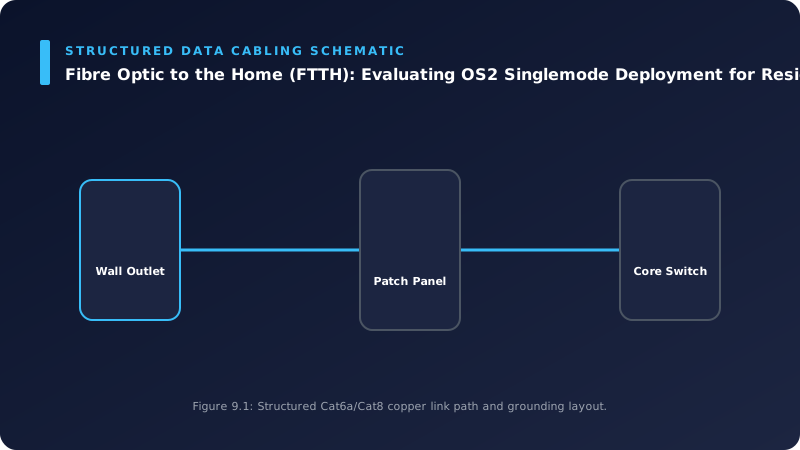
📊 Technical System Design Reference Infographic
Related Technical Resource: Forensic Video Retrieval: Best Practices for Evidential Chain of Custody in UK CCTV
Technical Standards and Industry Resources
- External Compliance Guidance: Industry Standards & Compliance Resources
- Partner Site Feed: Gary Pearce Portfolio Services - Wix Hub